 Optical
triggering module for slave strobe unit,
Optical
triggering module for slave strobe unit,compatible with "dual flash" digicams
Optical
triggering module for slave strobe unit,The coolpix like others
digicams fire 2 times his strobe when shooting a photography with flash. Then
classic slave strobe unit can't work correctly, because they fire on the 1st
flash on the digicam, and not on the second as they should do.
I've tried all the available modes on the cp880, even the "full manuel"
mode; the preflash is always used !
This problem can be solved
with somes specifics strobes units dedicated to dual flashs camera (see srelectronics.com),
but it's definitly not the cheapest way!
The solution i choosed, is to build myself my optical trigger module to drive
an old strobe unit i have (Sunpak auto 240). It's only cost time, but not too
much money !
I found on the internet (on the dpreview forum especially) a lot of contact with people who already have done this kind of electronic module. For more details, please visit the dedicated page.
Caution ! The schematics presents in my pages are shown without any warranty. The only thing i could say is that my 2 schematics works with my strobe unit. The "dual flash" version works with both my strobe unit and my coolpix 880. I never had try the other schematics...

Because,
first all my 74HC4017 has burned out (you will anderstand later on this page),
i started to debug a "simple" version of the module, only compatible
with camera wich doesn't use preflash.
It works correctly with a quite nice sensitivity in differents light conditions.
This slave fire even if the camera is far from 7 or 8m and not orientated in
direction of the slave.
Version 2 modification : 1µF replace by 2.2nF on multivibrator.
After anderstanding my problem of counter damages, i success to debug this new complete version, compatible with dual flashs cameras.
(New! version 5)
Version 4 modifications
: U1 pinning error fixed, 0.1µF replace by 1µF on multivibrator.
Version 5 modifications : correction ref LTR4206N (et non 4206E), 1k sur gate
thyristor au lieu de 10k, transil diode is not necessary
This schematics have been tested with success in different ambiant light conditions.
For some recents
strobes units, high voltage is no more present on trigger pins, because some
built in electronic drive this high voltage with thyristor or IGBT.
I recently bought a "METZ 32Z 2" witch is IGBT drived. To adapt my
module to it (Thyristor need high voltage to start conducting) i replaced the
thyristor part of the previous schematic by a "bipolar" version of
it, with the thyristor simply replace by a very common NPN transistor. I don't
know if this adaptation will also work with thyristor drived strobe unit...
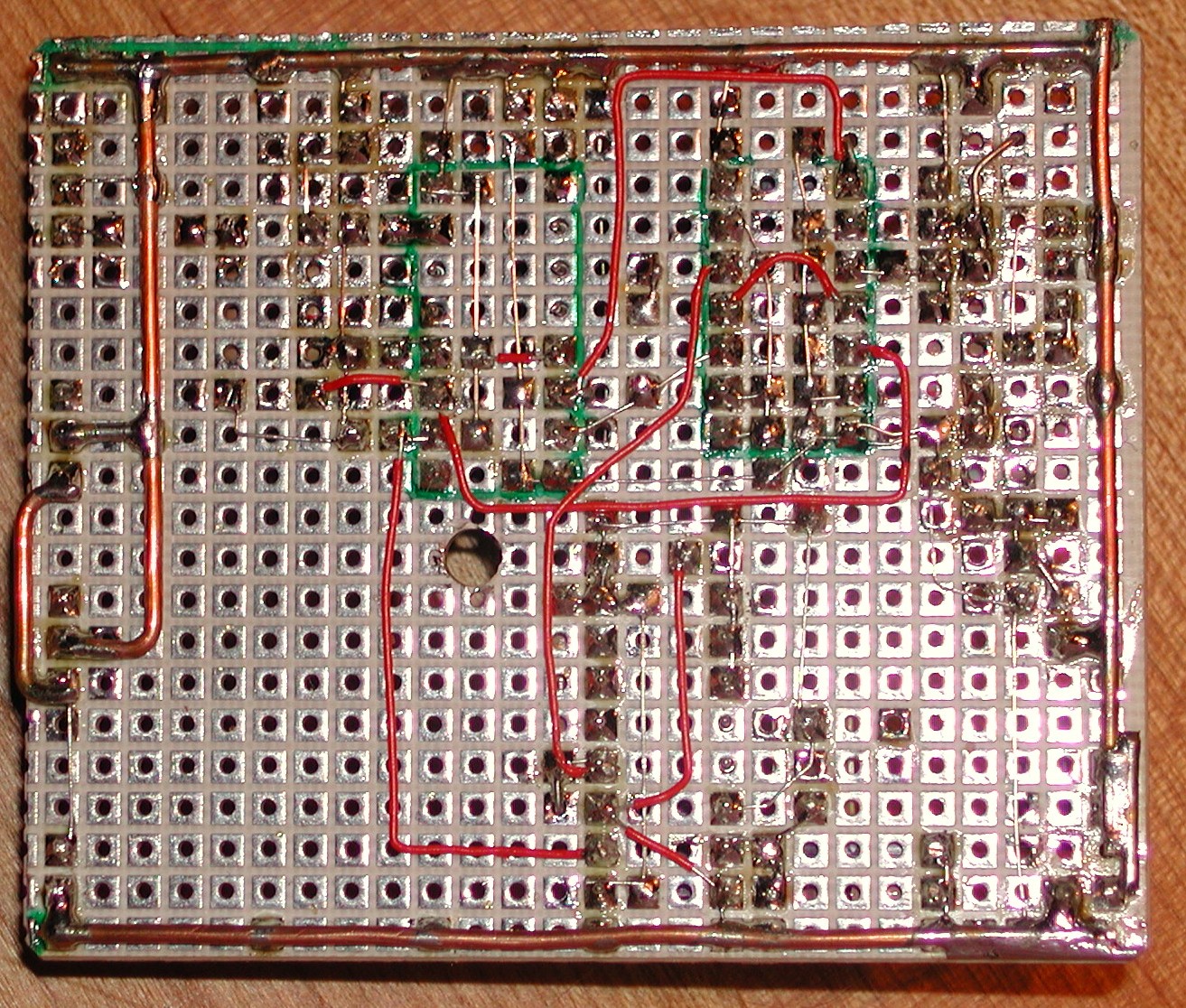
| Components side view | Cu side view | |
| n°1 (common strobe) |
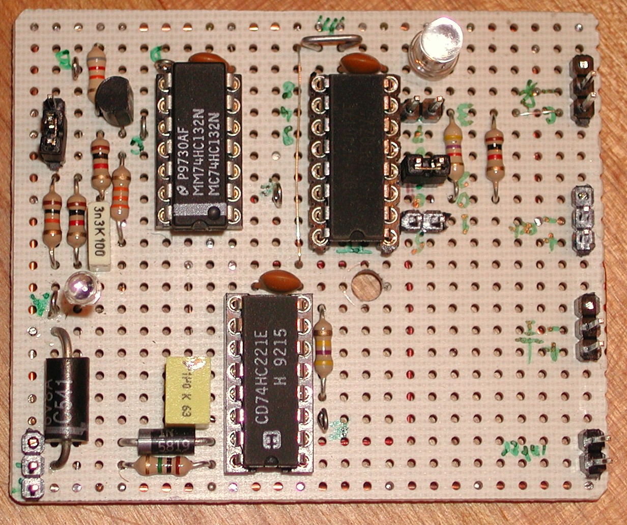 The thyristor is solded on Cu side of strobe shoe extension board |
 |
| n°2 (IGBT strobe) |
 |
 |
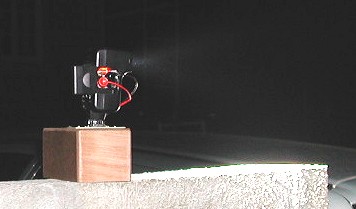
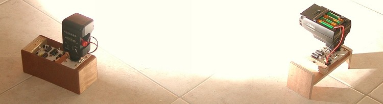
On left : common
strobe controlled by my thyristor module version
On right : Recent
strobe controlled by my bipolar transistor module version


Optical sensor
The phototransistor current increase if ambiant light luminance increase too. The higher is the luminance, and the higher is the voltage on tpA.
When i first watch the tpA voltage with the oscilloscope i saw 2 parasitics frequencies at 100Hz and 200KHz.
200 KHz parasitic :
The 200KHz generate a lot
of counting errors, but disappear after i supply my module with batteries rather
than by programmable AC power supply.
|
With AC programmable
power supply : |
With batteries supply,
|
100 Hz parasitic :
I first search on electric phenomena this 100 Hz parasitic. It can't be something relative to AC power line because the module is supplied by batteries. The only 50Hz or multiple present around the module was the light !
When the phototransistor is exposed to light comming from indoor classic lamps (AC line 50Hz 220Veff in France), it react in relation with light intensity witch is variable in this case. A lamp haven't got any polarity, then with 50Hz AC line a maximum voltage appears 2 times per period, then the light intensity frequency is = AC line frequency * 2.
50 Hz * 2 = 100 Hz.When the phototransistor is exposed to light comming from a pocket lamp using batteries, the 100Hz totally disappears.
module exposed to classic AC line lamp :

module exposed to pocket lamp :

Resistor setting :
The serial resistor with
phototransistor define the gain of the sensor. For the same current in the phototransistor,
the bigger is the resistor value, and the higher is the voltage on tpA.
1 kohms with 6V supply voltage is suitable for most common light condition,
however for a very dark ambiant light (outdoor inght shots without any moon
light) 10 kohms generate a higher sensor sensitivity, so remote distance between
camera and the trigger module can be increased. Don't think it also increase
sensitivity for brighter conditions. In fact the voltage on tpA becomes so high,
that it clamp to vcc. The sensitivity is then totally null !
To finish, lets say that 10 kohms is optional, but it could help...
High pass filter
principle of operation and calculation
A high pass filter is used
to activate the counter clock input only when a pulse appears with a rise time
short enough. Then the system is totally independant of the mean ambiant light
intensity and will detect each time the light is changing quickly. (It doesn't
start if you simply switch on the room light for instance).
The other interest of that, is to filter the 100 Hz parasitic coming from AC
line lamp.
 When
Vin doesn't change (or slowly enough), C is charged to Vin, then Vout = 0.
When
Vin doesn't change (or slowly enough), C is charged to Vin, then Vout = 0.
If Vin change quickly, C doesn't have time enough to be charged, the voltage
change is present on Vout. However due to dividor bridge R1&R2, the pulse
on Vin is reduced on Vout in respect with R2/(R1+R2) ratio.
The cutting frequency of this filter is defined by 1/(2*pi*R*C).
For R, 2 cases should be considered :
The equation to consider is "1/(2*pi*(R1+R2)*C)" because when Vout reachs vbe, it means that detection is effective (too late to filter or not). And the purpose of filtering is to define wether or not a voltage variation should be detected.
With R1 = 1Kohm, R2 = 18 kohms and C = 3.3nF, the cut frequency = 2540 KHz, wich is enough to filter efficiently the 100Hz parasitic. The R2/(R1+R2) divider with thoses values, enable a low pulse voltage loos. Vout max = 95% of Vin
100 Hz filtering
tpA
: 100Hz Before filtering |
tpB
: 100Hz after filtering |
I started with a first version with no R2 resistor. In that case an infinite value can be substitute in the cut frequency equation, wich indicate that the filter won't filter anything ! (there is no current to charge C until Vout reach a transistor vbe)
Other parasitics filtering
Some other parasitic signals needs to be filtered. When anything is agitated in front of the optical sensor, the light that reach it may vary quickly. If the high pass filtering cut off frequency is too low, somes pulses could appears on Vout (tpB). The next oscilogram show an example of that, with a pen agitated in front of the sensor and a filter made with 10 nF, 1K and 18K.
When the slope increase on tpA, the voltage on tpB increase.
Bad filtering means parasitic extra triggering !
After this trial, i choosed a smaller capacitor (3.3nF) to increase the cut off frequency, and then decreassing the module sensitivity to parasitic triggering.
with coolpix flash
However, with 1k, 18k and 3.3nF values, the cut off filtering frequency is higher enough to filter parasitic, and lower enough to pass the coolpix flash pulse. Thoses pulse are really quicker than parasitic, as you can see on both oscillograms below. Please note the very high positive slope on the pulse rising edge.
| With
a "long" coolpix flash (camera far from the main subject) |
With
a "short" coolpix flash (camera close to the main subject) |
|
| same x and y scales as the previous oscilogram above to compare |
 |
 |
 |
 |
Buffer
Interface to amplify signal to enlarge it enough to be compatible with logical input level of the next ship.
Schmitt trigger
Caution ! Scmitt trigger is absolutly necessary to avoid counter definitive damages !
HC type ICs power consumption is very low, except during logic state transition. If input voltage slope is low, the period of time when the input voltage is still near the input threshold voltage is long. During this critical period ("critical area" in the figure below), the IC may trigger several times because it could exists some ambiguity between input voltage and threshold (is the voltage bigger than the threshold or not ?).
I said before, that power dissipation on HC type ICs (MOS inside) is not low during logic state transition. So when multi-triggers appears, the dissipated power increase so much that definitive damages could happens. I destroyed, by this mean, four 74HC4017 counters !
The solution is to avoid ambiguity. Schmitt trigger are devices build for this. They have a variable input threshold voltage. When the input voltage reachs the threshold one time, this one decreasse immmediatly and the IC trig just one time (as it is supposed to). The threshold won't change until the input voltage start decreasing and reach again, but in the opposite direction, this new threshold. Then the threshold come back to his first value.
Without
Schmitt trigger : |
With
Schmitt trigger : |
So be carefull !!! With HC type ICs, please consider seriously your rise and fall time on inputs ! If the time is bigger than specification value, add a schmitt trigger before.
For more details
: ![]() HC
type user guide
HC
type user guide
Because the rise and fall time on tpC are too slow, i added a schmitt trigger on the counter clock input.
Counter
Nothing special to explain here about the way it works. It's a generic device. If you discover 74HC4017 for the first time and if you wan't more informations about it, look the datasheet. It's pretty well explained.
Some web surfer asked to me "why don't use some flip flop in place of counter?". Answer : Because i like the idea to be able to trig a strobe unit on the third flash (a single flipflop would be limited to the second). In term of number of components, i think that there is no gain to replace counter with filpflop. In both case you will need one IC package (14 or 16 pins doesn't change anything).
Reset timer
To avoid unwanted triggering due to other cameras shooting in the same place, or some hypothetic strong electrical perturbations, an "auto-reset" have been added. For people who could wonder if this kind of supplementary logic is really necessary, let's imagine a module that generate a systematic auto-reset after the counting reach 2. What happen if someone else takes a picture with his own camera witch generate only 1 flash ? I'm afraid that everything is then shiffted. The preflash will be considered as the second flash, the strobe is fired (it is not supposed to be). The real second flash is considered as the next first and the external strobe is not fired when needed !
My auto-reset happen if :
 It's
made by some logic gates that generates a rising edge on counter "MR"
(master reset) pin if :
It's
made by some logic gates that generates a rising edge on counter "MR"
(master reset) pin if :
3 gates are used. It could
have been done with a lower number of gates, but the NAND with schmitt trigger
used for the counter clock input, is supplied in quad gates package. So why
don't using it ?!
The multivibrator start his pulse on the first flash (rising edge of counter
"1" output), and finish after a delay determined by a RC resonator
on "R/Cext" & "Cext" pins. With actual values,
the measured pulse delay = approx. 200 mS
A schtocky diode is present to avoid IC damages during C discharging.
The timer trigger input "1B" doesn't need external schmitt trigger, because
one is included inside the IC and signal is comming from another HC type IC.
The resistor on the
1Q bar output is there to enable the module to work without any multivibrator
plugged into his socket, for debugging purpose without any counter reset.
I was first thinking to a NE555 but logic edges were opposites of my need and i like the idea to have all logic ICs in the same family, so the timer is a 74HC221.
Caution ! The theorical pulse duration for the RC choosed should be 700mS, but due to capacitor leakage probably, the measured value is about 200 mS. It could be interesting to check the multivibrator pulse duration with another capacitor type. The duration must be greater than interval between 2 flashs (approx. 100mS).
Thyristor
To drive common strobe
To fire a strobe unit, old cameras simply shortened strobe trigger mains pins. The problem here is that voltage present on thoses pins is usualy very high. A bipolar transistor won't resist. So thyristor (SRC) is often used for this commutation.
A sensible thyristor is used because his low gate current enable direct counter output driving. HC type ICs can drive 8 mA.
1 kohms serial resistor set 5mA (with vcc = 5v) maximum current, witch is 20 times more than expected thyristor gate current. Then commutation is quicker and so, more suitable to high voltage commutation.The TIC106M is working correctly with my sunpack 240 (40V is present on his trigger pins), but i suppose (i've never checked it) that it could drive higher voltages. Some strobe unit seems to present 200V.
TIC106M component is specified to drive several hundred of volts. (see datasheet)I recommand you to place the thyristor as close as possible to your strobe shoe (visit the SAM page for explanations). I placed it directly below the shoe on my module.
To drive more recent strobe unit
In few new strobe unit, the high voltage is commutated inside the unit. Then high voltage is not output from the unit. Instead trigger pins are controlled with low power signal. I won't explain in detail this driving approach, because i haven't got too much informations about it (tell me if you know something about it).
Because no high voltage exist on input trigger pins, thyristor can't be used (it need suitable gate conditions to start conduction, but also sufficiant voltage and current between his anode to cathode).
Instead of thyristor, i'd try a simple basic NPN transistor and it works. But don't ask me more...!
Caution ! I'm really not sure that it will works with other strobe unit than mine.
Please visit this page
Total cost = 15.8 Euros ! (taxes
included)
(1
Euro = very approximatly 1 $)
See bill of materials for more details.
Turn on your
strobe unit, your trigger module and set your camera to flash mode. Then shoot.
Easy no ?!
Yes
shooting with strobe light present on your picture is easy, but unfortunatly
it's really more difficult to reach the step where your pictures are always
well exposed and focused.
A lot of questions, but not a lot of answers !
What
happen during preflash ? I
don't know !
I don't think it adjust the exposition settings. So it's a mistake !
I probably missed something.
I already have success with this technic, thus my slave strobe unit is only
firing on the second coolpix flash.
The
most difficult thing to manage is the very capricious coolpix880 autofocus.
In dark conditions, the light is quickly not strong enough for the coolpix to
be able to auto focus or on an unwanted subject. So your picture could be almost
well exposed but with a very bad focus. One way to success is to find a subject
exposed to light for the coolpix to run his autofocus on it (half press the
button), and then to move your digicam back to your main subject (without releasing
the button to keep the adjusted focus) before shooting. Both subject should
be at an equivalant distance.
Perhaps an other solution to investigate would be to use an external portable
lamp to illuminate the subject during auto focus.
The
other difficulty is to adjust the exposure (but i really prefer to fight with
exposure problems rather than with auto focus problems). There is no closed
loop to automatically adjust it as it could be found on usual camera-strobe
pair.
With
optical trigger module, you will have to adjust camera and strobe separately.
Adjusting shuter speed on the camera doesn't give anything, because in the case
of flash photography, the exposure time is not defined by the shutter speed
but by the strobe light duration which is very shorter (few µS) compared
to the shutter speed. (when the strobe light is finished the camera shutter
is still opened but in front of a dark image). The only way to adjust exposure
on the camera is to adjust aperture. Unfortunately the coolpix 880 has got only
two aperture settings : The minimum value and the maximum. It's not sufficiant
to adjust correctly the exposure.
The
second solution is to adjust the strobe intensity. It could be done directly
on the strobe setting if it has been designed for. If it doesn't, the last solution
is to choose the strobe location that take care of the intensity you need. If
you need a strong light, strobe could be placed far from walls, with light in
direction of the subject. On the other hand if you need low light, strobe can
be moved back close to the wall, in the opposite direction of the subject and
so on...
The last solution to adjust
exposure is to adjust distance between strobe and subject.
At this point let's make a summary about exposure adjustement possibilities :
The technic i use the most is the strobe location. This is the method that give you the best adjustement range. To use it, you will need to build your own experience, but with time it's possible to learn how to predict the amount of light that will result from each strobe location. However several shoots are often necessary for each new subject to optimize the exposure adjustement.
If you have any questions, remarks or suggestions, please contact :

